The device and circuit on the photo relay for street lighting
Title: Lightening 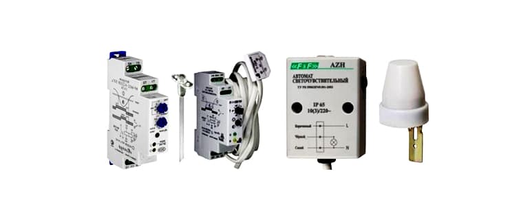
For yes, all oshiguri work on the body lighting in automatic mode, after some kind of device belonging to our automation equipment group, install it in the verigata for lighting. Commodity photorelay and relay for time, such as a sensor for movement, which is additionally included in the verigata for control of clarification.
Containment: 1. Which photorelay will you choose for street lighting 2. Where to install 3. Wiring diagram and configuration
Photorelay for street lighting - the topic on the tazi article, which has already examined the criteria for the selection of a product device, do not tell the schemes for connection, such as the location when using it.
Which photorelay will you choose for street lighting
The photorelay is a technical device designed and controlled to work on an electric chain through a shutter on the welded contacts under the influence of the sun light.
Base the elements on the device sa photocell (bright sensor), which has photosensitive properties, and an electronic unit, which processes and transmits a signal from the photocell.
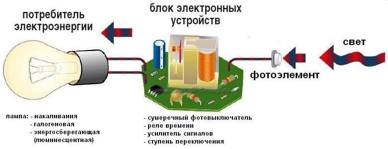 How the device works
A photoresistor or a phototransistor may be used as a sensitive sensor, depending on the verigat used in the production of a certain model.
The principle is to act on the product device, in order to lower the luminosity, the photocell is activated and the shutter is contacted, send a signal to the electronic unit, from which it signals to the control line on the connected equipment.
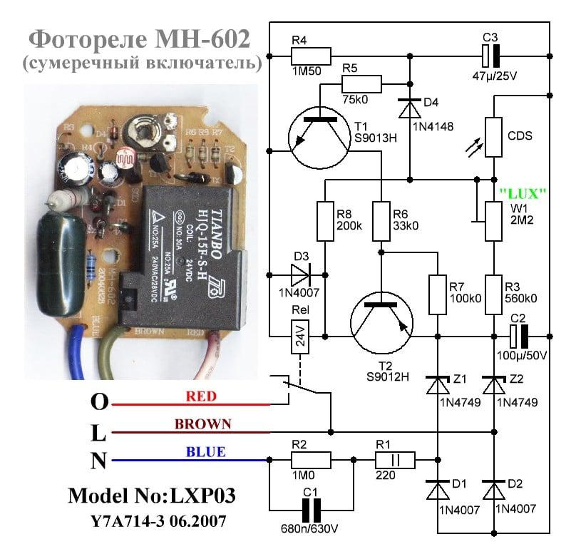
Principal diagram and visual view of the model, directed to the base at the phototransistor
The technical specifications for different models are different, but the main ones that you can characterize for using the device are as follows:
- work pressure on the guardian of the mrezha;
- electrical power for connecting goods;
- degree in case defense;
- temperature mode is in use.
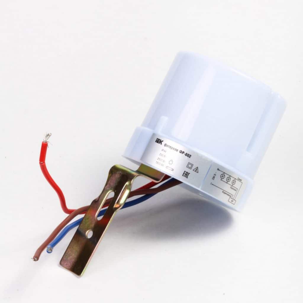
Inspection on the model "FR-602" with graded light sensor
According to its design, the photorelay can be made from a graded or remote photocell, which is determined by the ability to use it on a particular device.
Devices can and can be directed with pre-settings and the equipment itself, follow the control of the operation:
- prag on the reaction when painted-increased by light;
- zaksnenie when turned on, osiguryascho protection crossed false and alarms;
- regulirane for girth for illuminance.
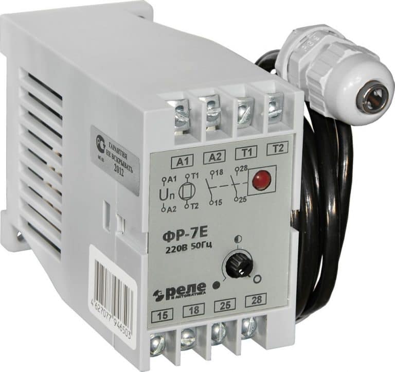 Extended look at the model "FR-7E" with extended light sensor
Criteria for selection on the photocell follow the parameters:
- Technical characteristics, which will determine the possibility of using and wiring diagram.
- Possibility for individual settings.
- Method on the installation (upper elements from the building structure or in the electrical equipment).
- The presence of additional controls, which expands the possibilities for using the device: a timer, a motion sensor and others.
- Price.
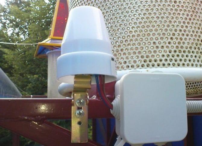 Installation of elements from the building structure in close proximity to the external lighting back kjm sdzharzhanieto ↑
Where to install
The choice of location for installation depends on the design characteristics of the device (the photocell is graded or removed), specify the technical characteristics and working conditions.
This device, designed and controlled, works on a single lighting body and has a photocell installed, then the installed windmill and all the bizarre things in the immediate vicinity of the control facility is located on the street. In this case, the case of vrazkata is directly carrying out the chain of custody on the external lighting body.
If the photoelectric relay is equipped with a remote photocell and is not intended for mounting on the top of a DIN rail, then it is placed in an electrical cabinet. In the last tryabva and assembly, the device was switched on (magnetic starter, contactor, etc.), through some kind of protection of the voltage by supplying the illuminator to the body. In this case, the device is also included in the control chain on the product including the device.
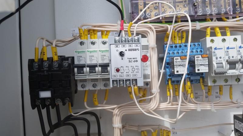 Placed in electrical cabinet
In case of damage to the installation work, the trip and all will be taken foresee the following points, which affect the work on the photorelay:
- if there is a photo sensor on the built-in sensor, it is necessary to connect the conductors, the trembling is even sufficient, put it in the necessary place for installation from the electrical cabinet, the device itself will be removed;
- for the installation of the trebva and to be protected from the impact on the exterior lights on the light from the artificial production (lamps for clarification, headlights on cars and other means of exaltation, etc.);
- Some of the elements for setting to the operating mode, the location on the photo relay are even convenient for the distortion of the operation (accessibility, height on the delivery from nothing to the hearth, etc.).
Wiring diagram and configuration
Ask how and if you wire the photo relay to the control chain for work on external lighting, the trebva and if it is set before purchasing, then the circuit diagram on the link to the device, depending on it, the purpose, technical characteristics and location of the installation.
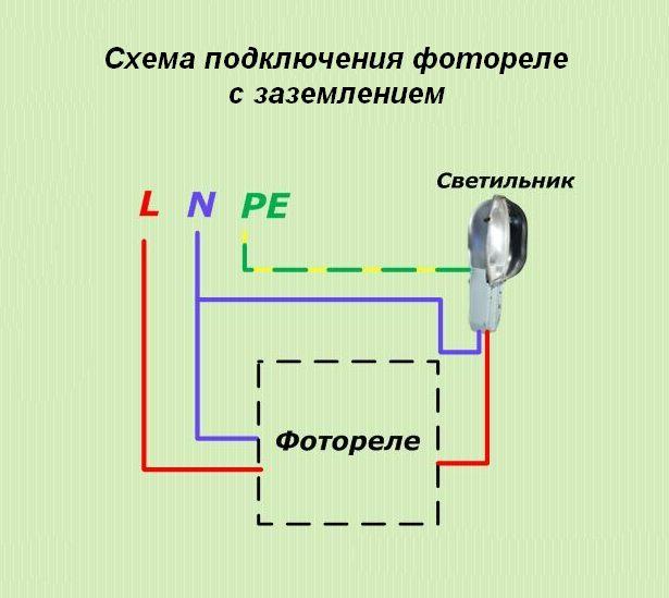
Scheme for linking directly to the storage of the chain on the lamp or spotlight
Whenever a device is directly connected to a light, the device is installed in close proximity to it. In the case of zero and the phase se, the contact is made to the relay from the protection of the electrical network, and the connection is made from the third contact.
When controlling the work on a group of lamps and a photorelay, it is connected to a contactor or a starter through the control chain, the work is delayed through the winding, which is located in the basket of the chain.
For your information! Operational voltage on the photorelay, used for controlling the operation of the contactor or starter, tripping and responding to the operation voltage on the reel on the control circuit for the switching on of the device.
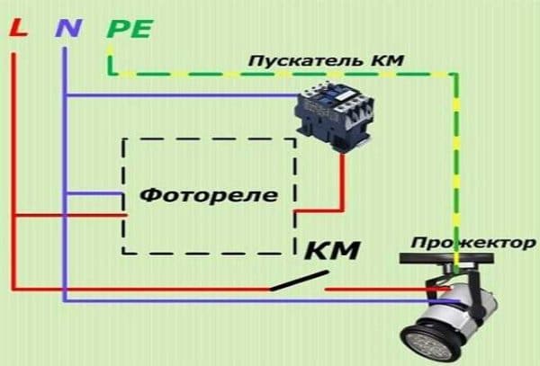 Scheme for switching on the control circuit to work on switching devices
The trace of the cato photo relay is mounted and tied, then it is shaking and it is regulated. It is adjusted with the help of the design on the trimmer device (pricks, turning controls, etc.).
For yes, send the comrade, at a given moment from time, corresponding to the clarification on the street, the setting is perverted through the turn on the adjustment of the elements, dokato turn on the lamp.
Manufacturers on the equipment for automation, as a rule, find in friendly documentation possible schemes for linking to their products, somehow start to regulate work and optimal places for work under various conditions.
PreviousLighteningHow to choose LED body lighting for closedNextLightingHow to choose 50w LED spotlight