The device and principle for the action on the ballast for fluorescent lamps
Contrary to recent developments in semiconductor technology, fluorescent lamps continue to be widely used. In the basin, we will analyze some of the ballast on the lampata. Let's take a look at the security element for every fluorescent lamp. Osvent coma, let's analyze the simple repair on tosi ballast.
containment: 1. What is the ballast and what is 2. Sortova 3. Options for the diagram on the link 4. Repair of electronic ballast for fluorescent lamps
What is the ballast and what is
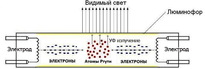
For yes, you will understand for some kind of ballast, tryabva and understand the principle of working on a fluorescent lamp (LL). Think for the neuron device. Structurally, every fluorescent lamp has a glass cap under the format on the tube, in the edges of which the refractory coils are sealed with a hot liquid, which is the electrode. Kolbat e polna with an inert gas with little added to the metal zhivak. From the outside, it is covered with phosphorus - a substance capable of emitting visible light when exposed to ultraviolet light.
 Construction and principle for action on LL
Whenever you put an electrode on it, you will see a sparkling discharge in the bowl. The flow from the electronics activates the atoms and they are only capable of radiating into the ultraviolet range. Ultraviolet light exposure to phosphorus, which shines brightly in the visible spectrum.
Samiyat ultraviolet se absorber from phosphorus and stakloto on krushkat. Do not get out of the border on the lampata. Tova eliminir has a harmful effect on ultraviolet radiation of the top of the horat.
On the theory vsichko e is simple.In the student, the lamp is turned off, once the voltage is applied to the electrode, the discharge is high and the voltage is high, and the resistance is condensed to the inert gas between the electrode and the solid high. With a starter run, the soil is completely vaporous, the resistance is on the gasy distance between the electrode of the sharp drop and the discharge in the bulb glows, turning into an uncontrollable arc discharge. For normal work on the lampata, tryabva and fulfill two conditions:
- Startiran.
- Support at work current prez kolbat.
Tova is ruled by ballasts, or ballasts, or ballasts. Without these, a single fluorescent lamp cannot work.
Sortova
Primarily cato ballast for a fluorescent lamp using an electromagnetic throttle (ballast) with a starter. Tozi kit beche named electromagnetic ballast - EMPRA. In terms of transistors and microcircuits, electronic analogies appear on electronic ballasts, performing a function. They call it electronic ballast (electronic ballast) or simply "electronic ballast". Think about the design and the principle of working on these ballasts.
Often EMPRA means self-electromagnetic throttle, which is not entirely true. EMPRA e throttle and starter - two separate blocks.
electromagnetic
EMPRA – tova e conventional choke winding, wound on a magnetic wire and a gas discharge lamp with a small size from the bimetal contact barrier (electrode operation).
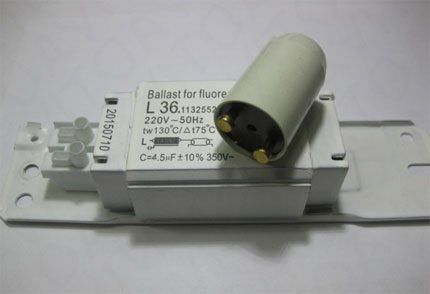 Throttle + starter = EMPRA
Please think about it, filtering through the lamp with electronic ballast. When you turn it on, in the starting flask, you start the discharge, some of the bimetal electrodes are dirty. As a result, on the tovar electrode, it will be welded and connected to the guard cell of the preddrosela on the spiral on the LL of the electrode.In this case, the discharge is illuminated in the crucible on the starting lamp from the gas.
Spirals on a fluorescent lamp heat up and their ability to emit electronics increases many times over. Contact the cato trace on the starter, they will cool it, they will boil it. As a result, a pulse with a high (up to 1 kV) voltage appeared on the line on the LL electrode, which was removed from the self-induction on the chokes.
 Typical scheme for a fluorescent lamp with EMPRA
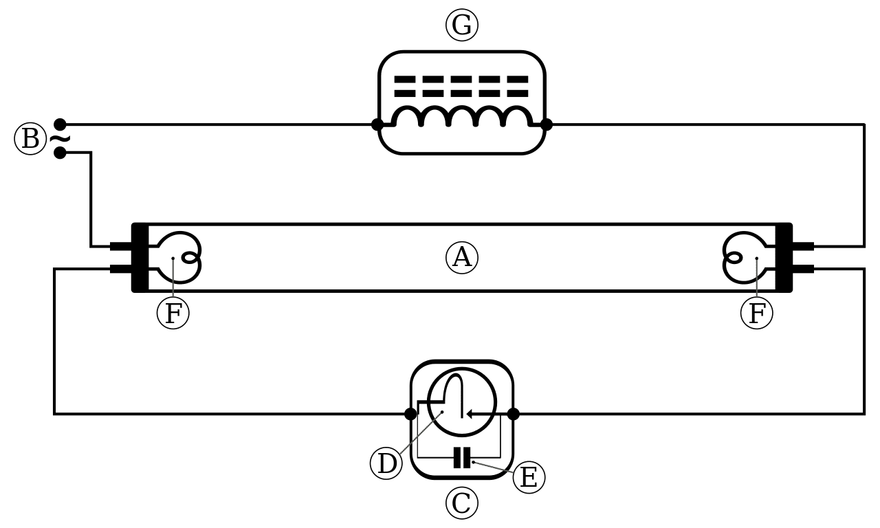
On the diagram, the letters show:
- A is a fluorescent lamp.
- B - AC network.
- C - starter.
- D - bimetal electrodes.
- E - sparking capacitor.
- F - niches from the cathode.
- G - electromagnetic throttle (ballast).
High breakdown voltage The soil is sparse in the flask LL. In the case of zhivakt, the change is in a vaporous state, the resistance is on the gasy interval of a sharp decline. In order to prevent the discharge from turning into an uncontrolled arc, it is limited by the choke with a clearly inductive resistance. Zatova se narich ballast.
Electronic
Externally, the electronic ballast for a fluorescent lamp is similar to electromagnetic. That ima has serious design differences and a different principle for working.
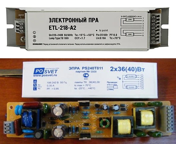 Electronic ballast (burned out) and unready "flnene"
Somehow you can see in the picture, there are a lot of radio elements in the electronic ballast. Let's take a look at a typical block diagram for an electronic ballast and let's see how it works.
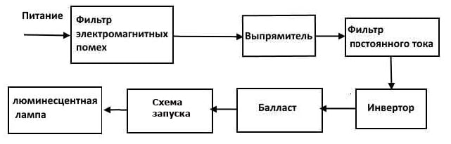 A typical block diagram on an electronic ballast
The current intermediary voltage is interrupted by the EMI filter, correcting it, erasing it, and supplying it to the inverter. Inverter task and osiguri voltage for work on LL. The voltage generated from the inverter is supplying the lamp to the converter for current limitation (ballast). Schematic for shooting it out of itself for launching on LL.A trace of the function of si, that of non-participation in natatshna work.
Take the inverter, ballast and starter into a conditional separation in a block diagram. Mostly function on the ballast from the inverter, which additionally serve as a current stabilizer. In some of the chains of that game, the role of the starter was played, regardless of the thrashing decision for attacking the spiral on the lampat and storing it from the start of the impulse with a high voltage.
Excuse me, start the chains as a conventional capacitor, which forms an oscillatory chain with a spiral and out of the throttle. Last set to inverter frequency. Resonance, rising when exhausted on the lamp, hanging the voltage on the electrode on the lamp to one or ten kilovolts and igniting the discharge into the flask without first catching on the spiral (student start).
 In the basin, the lampata of the starter is on the studeni of the spiral from the capacitor, which forms a resonant chain
What kind of scheme is this? On the first place, trepteneto. Conventional electromagnetic choke for lamp storage with 50 Hz changing current. Phosphor has low inertia and in the interval between half-lights, lightly ruin the brightness for radiance. As a result, this fluorescent lamp is white. Tova e losho for vision.
It is especially trembling when the lamp wears out, some phosphorus destroys its inertial properties.
Inverter, save LL, work on the frequency from the deset and dory statistic kHz. In this case, the inertia on the phosphor e is sufficient, for yes, “from the very beginning”, pause between the impulses on the storage without a gap in the brightness. Toest, thanks for the electronic ballast, fluorescent lamp and low pulsation coefficient.
The Osventov electronic circuit of Osiguryav is stably stored on the lamp, but the voltage is different from the nominal one. For example, the POSVET electronic ballast (view the picture from the top) allows for LL and work at an intermediate voltage from 195 to 242 V. If the lamp is connected through the electronic ballast, at such a voltage or even less exploitation, or it is not yet ground.
Options for the diagram on the link
Razgledahme verigata for connected to a fluorescent lamp and an electromagnetic ballast. Toy e is standard and without variation. Equipped with a sedan with a condenser, fixed on the lighting rod. That serve for painting on reactive power, consumer from all reactive goods, including drosela.
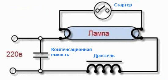 Diagram for a fluorescent lamp with an electronic ballast and a compensation capacitor
Two fluorescent lamps can be connected to each other by a single throttle. In this case, try and try and follow the conditions:
- LL
- The ballast power is equal to the sum of the power on the LL.
- LL sa design for a working voltage of 110 V (sometimes it is protected from 220 V).
- The starter is designed for operating voltage 110 V.
The diagram for connecting two lamps to a single choke is the following (the power for the choke is 36 W and the lamp is 2 × 18 W conditionally):
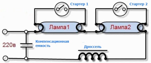 Lighting chain with two fluorescent lamps per EMPRA
Important! For effective reactive power compensation, it is necessary to select a capacitor with a suitable capacity. Depend on the power of the lighting rod. For example, a 18 W lamp and a 4.5 μF capacitor. In a lamp with 60 W, the lamp has a capacitance of 7 μF. Capacitor the condenser and sa non-polar and design for operation a minimum voltage of 400 V. It is usually used by the MBGO and MGP condenser charters.
Thy kato electronic ballast, as a rule, holding a starting device, f-forest and svrzhet LL to him. For yes, shove the illuminating body, and shake the conductor itself. Nay-forgive the example of a single lamp, a single electronic ballast.
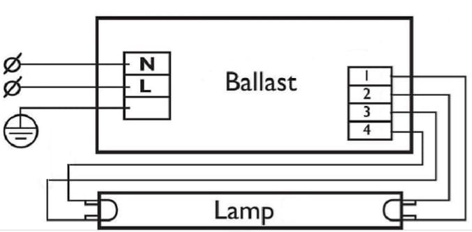 Standard circuit connected behind LL through electronic ballast
Ima balasty, who work with lots of lamps. For example, in the valley of the sa, scheme on the connection for electronic ballast for 2 LL.
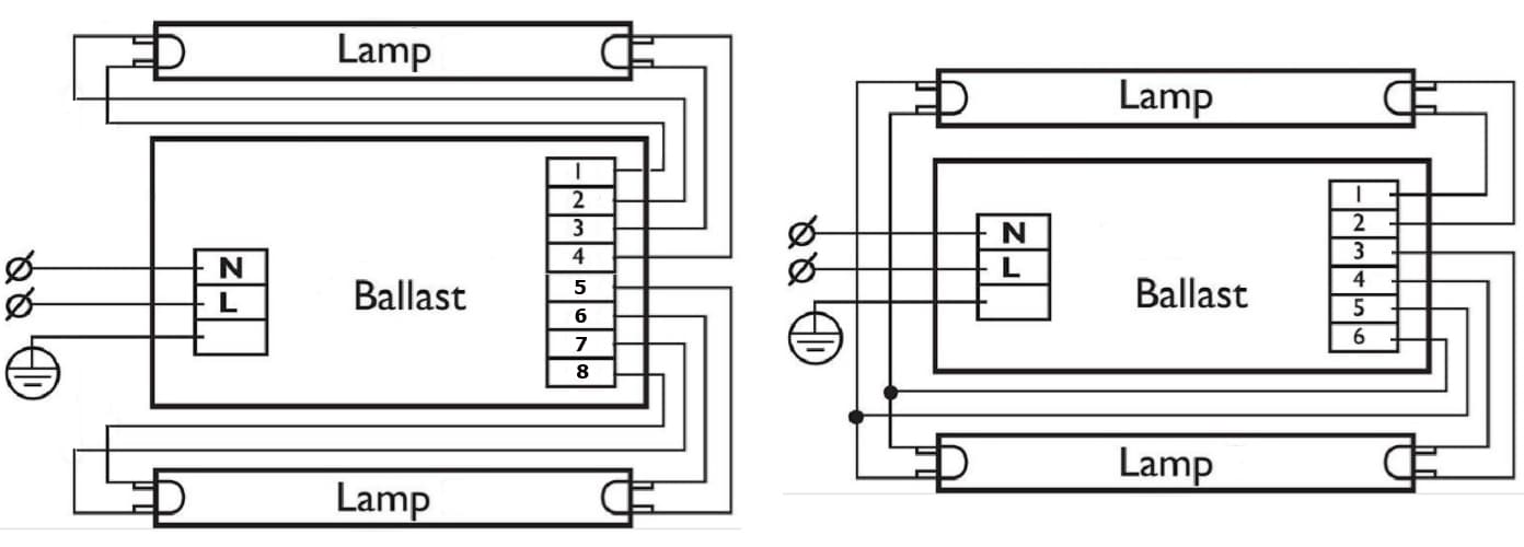 Possibilities for joining the ECG for two lamps
Schematic for svyarzvane on the ballast, designed to work with four LL, from the following:
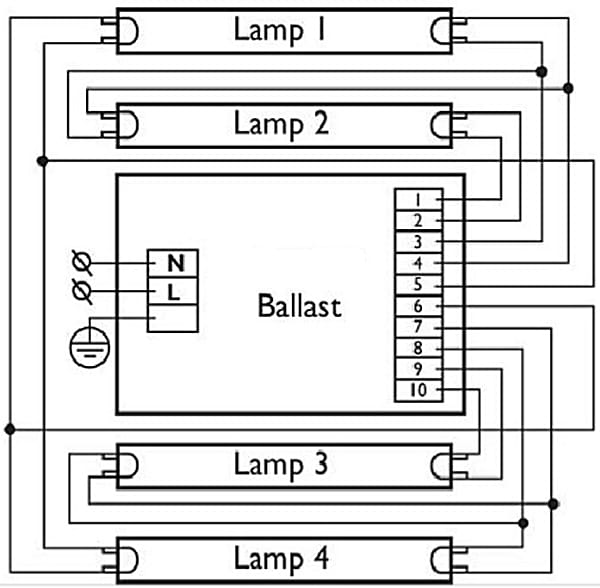 Scheme for connecting to the ballast for 4 luminescent pins
Universal devices, depending on the switching circuit, can and work with any LL switch with different power.
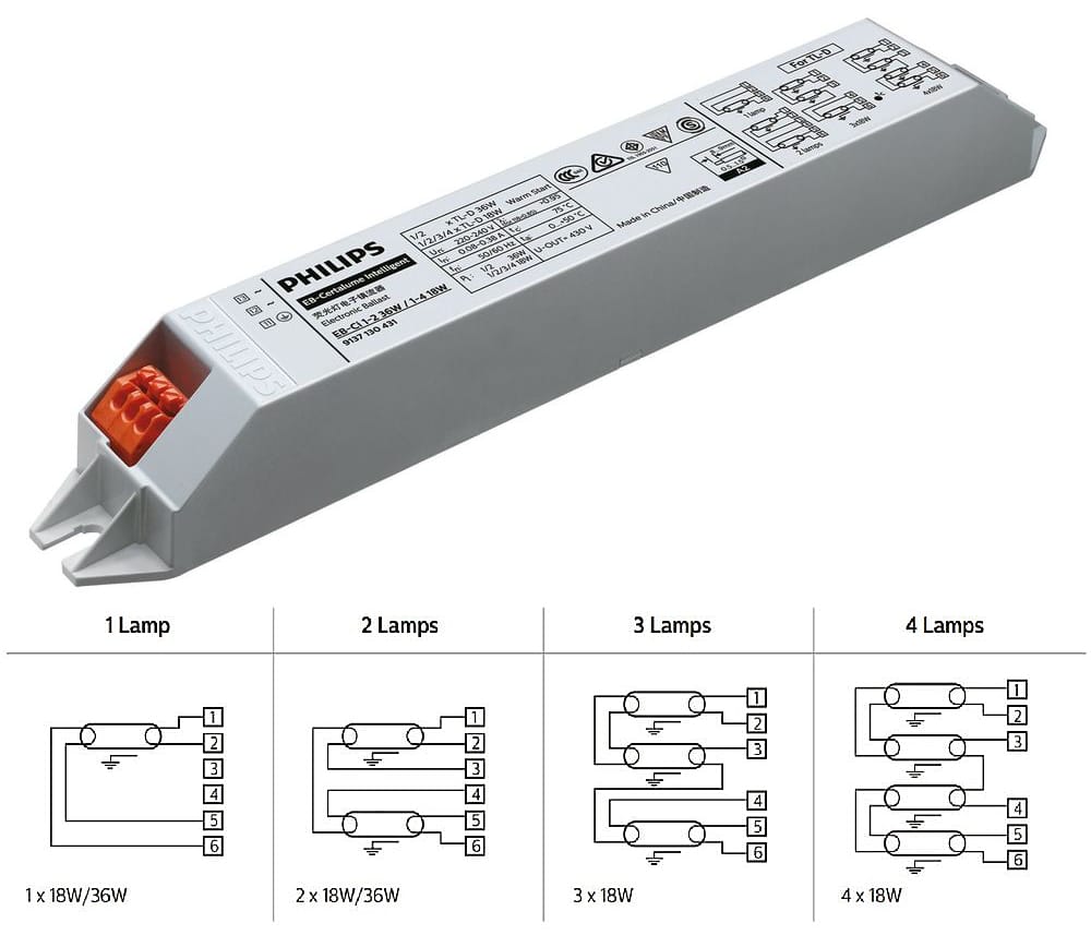 Universal ballast and circuits for it are ready to be switched on
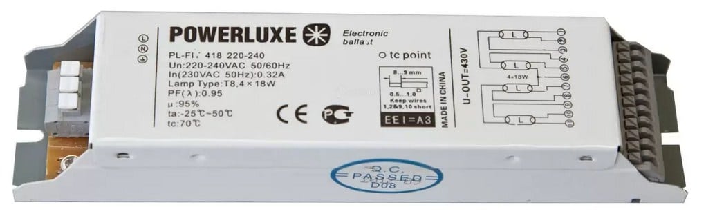 Scheme for connection to electronics ballast se namira on hulls mu back kjm sdzharzhanieto ↑
Repair of electronic ballast for fluorescent lamps
Before you fix the ballast, you will assure yourself that the problem is not in the samata lamp. It's not difficult, but check the correctness on LL. For the whole time, from the lamp and ring the cathode of the spirals with all the tester to the mode on the measurement for low resistance. Ako imame taka naming CFL in riyet si, then we’ll break it down even more, and then we’ll pick up a spiral. When checking on the two sides of the spiral, the device is shaking and showing resistance from a few units to a few tenths of an ohm (depending on the power of the lamp).
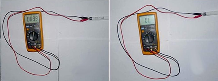 Check for integrity on the spiral on the cathode LL with multicet
Ako is missing from the spiral, do not “ring”, the lampata is defective. In the picture in a mountain, slack, spiral work, in a clear way - into a rock. LL don't work and it's impossible to fix it.
Malfunctions on the LL can even be due to decay on the active layer, attached to the top of the helix, despite the fact that they still ring. At a certain time, the voltage at the starter running on the lamp and the work voltage is sharply increased. Electronic ballasts cannot and will not osigure. But such malfunctions do not appear unfun. The lamp began to shine strongly, spontaneously restarted and, as a result, it went out completely.
General schematic diagrams
Before you forget the repair, think for a little while crossing electronic ballast chains for fluorescent lamps. We’ll bury some with nai-sorry. Used in all low power illuminators, including compact fluorescent lamps (CFL).
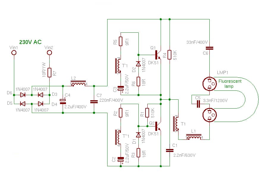
Scheme for an ordinary ballast for a fluorescent lamp
The intervoltage is corrected from the diode bridge D3-D6 and is removed from the high-voltage capacitor C4. The pre-filter switches L2, C7, which protect the blocking generator, are connected to the transistors Q1, Q2 and the transformer T1. The work frequency for the generator is usually 10-20 kHz. Pulsed voltage, taken from the winding T1, by applying the pres- t of the inductor L1 to cathode the conductors on the fluorescent tube LMP1. Repeat the exhaust on the cathode with the connection through the capacitor C5.
The trace was given to protect the chain of the starter generator. Km cathode on the lampat all applying voltage with honesty on the conversion. Dokato in the kolbat yama discharge, then premining the prez spiralite and C5. The capacity C5 is chosen so that it is connected with winding LMP1, choke L1 and winding T1 and forming an oscillator chain, tuned to the frequency of the generator. As a result of the resonance, the voltage on the cathode is increased to 1 kV. Vznikva razrushvane on a gas-filled distance in a kolbat - a lampata starter.
For the sake of low resistance to rarefaction in the bulb, the capacitor C5 of the manipulator, resonance of this decay and the operating voltage, it is necessary for LL, supplying the electrode to it. The current prez of the LMP1 crank is limited from the L1 throttle.
This work is done on a temple choke, which is modest in size compared to an electromagnetic ballast operating at 50 Hz.
Tazi scheme oshiguryava student start on lampata. That is, that se fuse without preliminarily polluted on the cathode and almost instantly. This is not the optimal mode, but it is drastically reducing the abdomen by LL. Now there is a diagram to be seen.
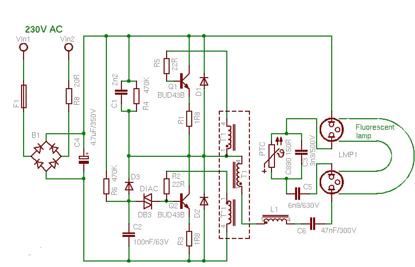 Simple ballast circle with heated coil
Kato tsyalo verigata e syshchata is similar to the principle of action. Intermediate tension of the corrigier, mowing and supply of a generator, which is from its own country, LL. But pay attention to the thermistor, capacitor C3 is connected in parallel with the starting point. The thermistor is positive TCR (such is the device of the se- nary is also a posistor). Dokato e studen, low stability. When you put on the storage of the lamp, the posistort of the C3 shunt and did not resonate, it will heat up the working voltage, which is not enough, but forming a discharge into the LMP1 coil.
The trace is known to the time of posistorat se heating from the current, contrary to it. Oppose mu people. Capacitor C3 of the spiral is manoeuvrable, resulting in resonance. The voltage on the electrode is increased to 1 kV. Nastupva breakdown into gas propep in kolbat - lampata all inclusive.
In the future, at the time of work on the lamp, often from the current, the presistor is interrupted, maintaining it in a heated state, so do not stop working on LL.Tova draws efficiency on the construct (energy is spent twice for heating on the posistor), but the differences are negligible - the resistance to heating the thermistor is golyamo, and the current is negligible. In addition, those are justifications for repeatedly increasing the operating stomach on a fluorescent lamp near the beginning of the “correct” start.
In conclusion, let’s take a closer look at the complicated and “smart” electronic ballast chain, a specialized microcircuit is slobena at the top. Approximately so, the ballast is more discussed in the section "Options for the diagram on the link". There, moreover, the positioning of the kato is universal and you can work with an arbitrary bray LL with different powers (from 1 to 4).
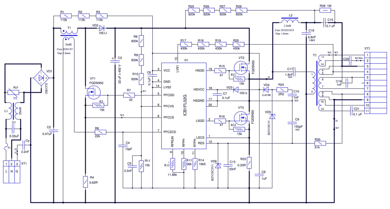 Universal electronic ballast diagram
For yes, let's analyze the principle on the work is not good, we need from the diagrams on the option for the connection to the lamp and the tosi ballast.
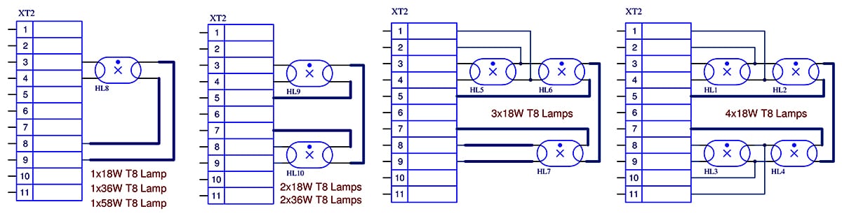 Schemes on the connection to the universal electronic ballast
The work on the ballast with LL e is divided into three stages:
- Pre-stained on the cathode.
- Rest.
- Mode for work.
The track is switched on to a stored generator, is globbed to a D1 microcircuit, a starter with a frequency of about 65 kHz. The signal to the generator through the preswitch on the protection, is connected to the half-bridge chain on the transistors VT2, VT3, supplying the transformer T2 and following the coil on the LL cathode, pre-heating the cathodes.
The track is determined by the time (adjusted by the resistor R13) of the clock on the generator for the ground and painting. In the next step, the cathode falls to the resonant frequency, which is tuned to the L2C16 verigata, then increase the voltage in the cathode on the lamp to 800 V. In the bulb, the discharge is more– LL starter. In this case, there is still a voltage on the shift 13 D1, some of the starter's third stage is work.
As soon as the switch 13 on the microchip did not appear, and on pin 1 it fell under 0.8 V, the process was repeated on the ignition. In case of some failure, the experiment for igniting the electronics will ballast the spiral and work and eliminate the defective lamp. Something else happened, sometimes you experiment and start the electronic ballast without a lamp.
If the start of the clock on the generator is successful, it will be painted until the clock is running (set from the resistor R12). Tokt prez lampata se stabilizer and support on given nivodori with significant fluctuations in the protection of voltage (for tazi veriga – 110 to 250 V). On the T1 and VT1 elements, there is a global corrector for active power, which draws a reactive component.
Typical malfunctions and tyahnoto removed
Now you are repairing the ballast on a fluorescent lamp with your own right now. Let's not forget the complicated malfunction - it's a work of definition of knowledge and device, but we can do it all right with the problem. Yes, we see some kind of nai-chesto, this is a departure from Comrade, something we can, let’s intend and fix it:
- installed with good quality;
- prepositional;
- capacitor for high voltage;
- current converter;
- power transistor;
- throttle / transformer.
So, razglobyavame ballast and correct visual check. All the elements, watch and drink the tryabva and sa in a good state – without a trace of deformation, darkening, destruction and aging. The picture is perfectly visible along the length of the image (clearly over the top and at the top of the hill):
 Faults on the ballast through a visual check
- poor quality soldered;
- blow on the smoothing condenser;
- burnt out drosel;
- the transistor is broken (frequently from kutiyata e iztrgnata).
Let's open takiva elementi, nie gi promename. Namirama is not calm - kalaidiswame and drunkenness.
Now we can see how to burn the elements on the scarf on the driver. They can be located in different places depending on the model on the ward, but the difference is usually insignificant. Namiraneto on wishes from you the article is not difficult.
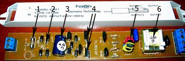 Approximate location of the main elements and electronic ballast board
In the picture, the numbers show:
- 1 – prepositional;
- 2 – diode bridge;
- 3 – smoothing the condenser;
- 4 – power transistors;
- 5 – impulse transformer;
- 6 – drosel.
Now we’ll take the tester in the tester and check the predpasit (ako ima taqv), without even unsoldering the verigat. The instrument tripped and reported to low resistance mode or diode mode. On the contrary, the prepositional case is defective.
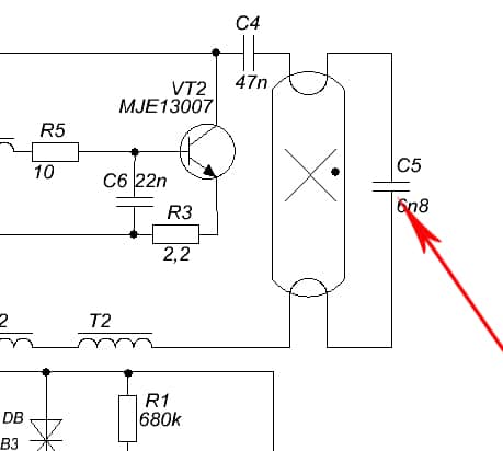
Current rectifier Maybe yes, all together or on a separate diode, or a collection of four diodes in a single package. In the picture, along the length of the montage, the arrow is marked.
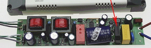 Tosi electronic ballast equipped with current converter
In any case, let's call on all the diode in the door with the tester, switched on in the semiconductor and test mode. In the first place, the device is shaking and showing a decline in voltage, then from order to a nakolkostotin millivolt, in another – Boundless. It is not necessary to unsolder the diode before testing.
Capacitor. Tosi element from the katomals to the bridge to the current rectifier. Dory and ugly goodness (not nabbnal or exploited), check it out. For yes, let’s send it, we’ll send the capacitor from the verigat and let it go into the mode on the power supply to the diode, after that we briefly mixed the conductor, for which we’ll dissolve it.
At the first moment, the device will even show a little resistance to voltage drops. Thy kato condenser is a charge, they will increase it.If the testimony of a sled is not going to be changed, the condenser is a poor one. Ako multitsetat showing the boundless, togawa condenser is open. And in two cases, the change of the element.
transistors. Those still tryabva and get out of steam for checking. Let's turn the multicet into diode-powered mode and connect to the transistor between the terminals on the base collector and the base emitter in the door of the switch. At the same time, the device will even show a drop in voltage, from the order of a few millivolts, to another – Boundless. Exhaust the collector-emitter from the general not trebva and ring - in the dvete shoals of boundlessness.
Tova e vsichko, we can send something, for yes we will help on electronic ballast. For yes, identify and overcome more complex faults, more help is needed from a specialist.
Razbrahme for how to serve the ballast on a fluorescent lamp. We will learn how to do these ballasts, how they work, we will learn how to overcome the faults on the electronic block.
PreviousFluorescentRegulations for the storage of fluorescent lamps in the enterpriseNextLuminescent How does a fluorescent lamp starter work?